
 Image 1 of 5
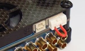 Image 2 of 5
 Image 3 of 5
 Image 4 of 5
 Image 5 of 5
Code: Mauch-030
Mauch 030
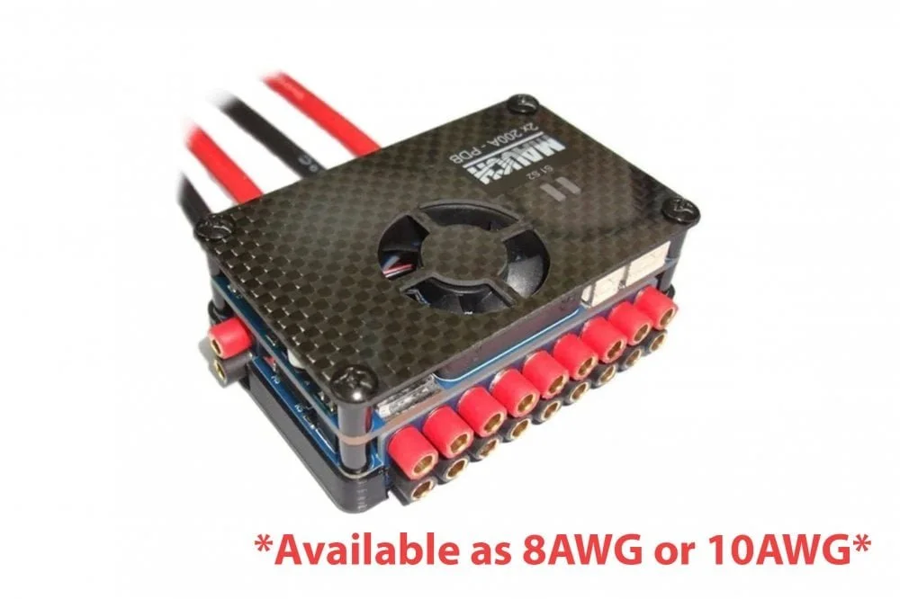
*Please select version required. Available with 8 AWG or 10 AWG input cables*
All-in-one PDB for Pixhawk 2.1 (The Cube) and any other flight controller via an adapter cable. With an integrated 2x200A hall sensor, Sensor Hub X2, 4-14S HYB-BEC, and most importantly a main power switch with a continuous current of 400A. The outputs are over 3.5mm banana connectors, plus spare BEC connectors after the switch and before the switch.
This design lets you connect the main batteries to heat up the Cube and get GPS lock without powering up all the rest of the equipment. When ready, just press the power switch and fly.
Less wiring = Cleaner builds
Protect your ESC’s and other equipment due to smooth power-up from GND.
Recommended maximum AUW of UAV = 50kg.
Specifications
Input 2x 4-14S (absolute max.60V) with transient spikes of max. 65V.
2x 200A = 400A (continues) 1,200A @ 25’C for 1sec.
Hub X2 can be deactivated for single battery usage.
5.3V / 3A power supply for Flight Controller
2x 20cm input cables (red/black) 10 AWG or 8 AWG
Only 75 x 49 x 27mm -> 110g (without cables)
Package contains
1x PDB with soldered-on input wires
1x 042: PL – FC cable for Pixhawk 2.1 (The Cube)
20x 3.5mm bullet connectors (male)
2x 26cm Red/Black shrinking tube
2 pairs AMASS / AS150 connector
REM: Delivery without 059: Power-Switch
Installation:
The PDB can be screwed to the vehicle’s frame. Removing the 4 bottom M3x12 screws and drill holes into the frame. Reinstall the screws though the frame. Exchange the screws to M3x15 (included) for frames thicker than 3mm.
Please reserve approx. 15mm free space in front of the bullet connectors for the output cables.
IMPORTANT:
The output connectors are 3.5mm bullet and the max. continues current per pin is 40A (50A spike). If you have any device which requires a higher current, then please consider to use multiple outputs in parallel, or solder a higher gauge wire directly into the female connector.
It is possible to solder up up 10AWG into the female connector and that increases the max. current per pin to 200A.-> With 12AWG it is 100A.
If you have any high current device, then please use the outputs in the middle of the PDB to ensure an balanced current flow through the PDB.
Select the correct voltage measurement range according your main battery.
Solder bridge out = Up to 14S (max. 60V)
Please use the voltage divider from the final test result (approx. 26.6)
Solder bridge in = Up to 7S (max. 33V)
Please use an voltage divider of 10.0 -> The measurement will be quite accurate. However, you can measure the main battery voltage with an DVM and readjust if necessary.
1: Main input for hall sensor 1 (max.60V) 200A continues.
2: Main input for hall sensor 2 (max.60V) 200A continues.
3: External BEC directly connected to main battery without main switch.
4: 9x output after main switch. For up to 8x ESC's plus one external BEC.
5: Power Switch 059, or if not connected then dummy connector to deactivate X2.
6: Sensor Hub X2 relays alarm output.
7: To flight controller (+/+/I/U/-/-) with Molex Click-Mate 1.25mm / 6p
The PDB is delivered without attached shrinking tube. Please select if you want to insulate the outputs with a small piece of it, or if you first want to insert the bullets and then cover the output incl. the bullet with one piece of shrinking tube. The included tube is dual wall adhesive shrinking tube.
For safety reasons, please protect unused outputs with a small piece of shrinking tube.
Important !
The top row is positive (red) and the bottom row is negative (black).
Status LED's:
During boot up the internal Sensor Hub X2 will perform an internal test:
RED -> Flashing RED -> If all OK, then GREEN for 1 second. (Both LED's)
After that, the LED status is depend on the current flow and if the current of both main batteries is within acceptable tolerance.
Flashing GREEN (Both LED’s) -> The current flow is below 3-5A per sensor and the X2 is in standby.
Solid GREEN (Both LED’s) -> The current flow is above 3-5A per sensor and the X2 is monitoring the main batteries.
If either one of the two main batteries will reduce the supplied current by approx. 20% than the other battery, then the LED of this sensor (S1 or S2) will change to solid RED and the alarm relay is on.
The alarm can be canceled, by either rebooting the PDB/Sensor Hub X2 (power cycle), or reduce the current flow to below 3-5A per sensor and wait 1 minute. -> If the Sensor Hub X2 is 1 minute in standby then he will reset any existing alarm and switches off the alarm relay.
Deactivate Hub X2 for single battery usage:
If you use the optional Power-Switch, then the Hub X2 can be deactivated by pressing the power switch for 3 seconds. Both LED's (S1/S2) will change to solid red to indicate that the battery monitoring is deactivated. The alarm relays will not be activated.
A power cycle will reset the X2 to normal operation.
If the Power-Switch isn't used, then please connect the dummy connector (see picture) into the switch output. This will deactivate the internal alarm and both LED's change to solid red.
The Hub X2 will be always deactivated until you remove the dummy connector.
Setup in MissionPlanner (see photo)
Please follow the procedure here: http://ardupilot.org/copter/docs/common-mauch-power-modules.html
Code: Mauch-030
Mauch 030
*Please select version required. Available with 8 AWG or 10 AWG input cables*
All-in-one PDB for Pixhawk 2.1 (The Cube) and any other flight controller via an adapter cable. With an integrated 2x200A hall sensor, Sensor Hub X2, 4-14S HYB-BEC, and most importantly a main power switch with a continuous current of 400A. The outputs are over 3.5mm banana connectors, plus spare BEC connectors after the switch and before the switch.
This design lets you connect the main batteries to heat up the Cube and get GPS lock without powering up all the rest of the equipment. When ready, just press the power switch and fly.
Less wiring = Cleaner builds
Protect your ESC’s and other equipment due to smooth power-up from GND.
Recommended maximum AUW of UAV = 50kg.
Specifications
Input 2x 4-14S (absolute max.60V) with transient spikes of max. 65V.
2x 200A = 400A (continues) 1,200A @ 25’C for 1sec.
Hub X2 can be deactivated for single battery usage.
5.3V / 3A power supply for Flight Controller
2x 20cm input cables (red/black) 10 AWG or 8 AWG
Only 75 x 49 x 27mm -> 110g (without cables)
Package contains
1x PDB with soldered-on input wires
1x 042: PL – FC cable for Pixhawk 2.1 (The Cube)
20x 3.5mm bullet connectors (male)
2x 26cm Red/Black shrinking tube
2 pairs AMASS / AS150 connector
REM: Delivery without 059: Power-Switch
Installation:
The PDB can be screwed to the vehicle’s frame. Removing the 4 bottom M3x12 screws and drill holes into the frame. Reinstall the screws though the frame. Exchange the screws to M3x15 (included) for frames thicker than 3mm.
Please reserve approx. 15mm free space in front of the bullet connectors for the output cables.
IMPORTANT:
The output connectors are 3.5mm bullet and the max. continues current per pin is 40A (50A spike). If you have any device which requires a higher current, then please consider to use multiple outputs in parallel, or solder a higher gauge wire directly into the female connector.
It is possible to solder up up 10AWG into the female connector and that increases the max. current per pin to 200A.-> With 12AWG it is 100A.
If you have any high current device, then please use the outputs in the middle of the PDB to ensure an balanced current flow through the PDB.
Select the correct voltage measurement range according your main battery.
Solder bridge out = Up to 14S (max. 60V)
Please use the voltage divider from the final test result (approx. 26.6)
Solder bridge in = Up to 7S (max. 33V)
Please use an voltage divider of 10.0 -> The measurement will be quite accurate. However, you can measure the main battery voltage with an DVM and readjust if necessary.
1: Main input for hall sensor 1 (max.60V) 200A continues.
2: Main input for hall sensor 2 (max.60V) 200A continues.
3: External BEC directly connected to main battery without main switch.
4: 9x output after main switch. For up to 8x ESC's plus one external BEC.
5: Power Switch 059, or if not connected then dummy connector to deactivate X2.
6: Sensor Hub X2 relays alarm output.
7: To flight controller (+/+/I/U/-/-) with Molex Click-Mate 1.25mm / 6p
The PDB is delivered without attached shrinking tube. Please select if you want to insulate the outputs with a small piece of it, or if you first want to insert the bullets and then cover the output incl. the bullet with one piece of shrinking tube. The included tube is dual wall adhesive shrinking tube.
For safety reasons, please protect unused outputs with a small piece of shrinking tube.
Important !
The top row is positive (red) and the bottom row is negative (black).
Status LED's:
During boot up the internal Sensor Hub X2 will perform an internal test:
RED -> Flashing RED -> If all OK, then GREEN for 1 second. (Both LED's)
After that, the LED status is depend on the current flow and if the current of both main batteries is within acceptable tolerance.
Flashing GREEN (Both LED’s) -> The current flow is below 3-5A per sensor and the X2 is in standby.
Solid GREEN (Both LED’s) -> The current flow is above 3-5A per sensor and the X2 is monitoring the main batteries.
If either one of the two main batteries will reduce the supplied current by approx. 20% than the other battery, then the LED of this sensor (S1 or S2) will change to solid RED and the alarm relay is on.
The alarm can be canceled, by either rebooting the PDB/Sensor Hub X2 (power cycle), or reduce the current flow to below 3-5A per sensor and wait 1 minute. -> If the Sensor Hub X2 is 1 minute in standby then he will reset any existing alarm and switches off the alarm relay.
Deactivate Hub X2 for single battery usage:
If you use the optional Power-Switch, then the Hub X2 can be deactivated by pressing the power switch for 3 seconds. Both LED's (S1/S2) will change to solid red to indicate that the battery monitoring is deactivated. The alarm relays will not be activated.
A power cycle will reset the X2 to normal operation.
If the Power-Switch isn't used, then please connect the dummy connector (see picture) into the switch output. This will deactivate the internal alarm and both LED's change to solid red.
The Hub X2 will be always deactivated until you remove the dummy connector.
Setup in MissionPlanner (see photo)
Please follow the procedure here: http://ardupilot.org/copter/docs/common-mauch-power-modules.html